Stepper Motor Basics: Types, Uses, and How They Work
This article will introduce you to the basic knowledge of stepper motors, including their working principles, construction, control methods, uses, types, and their advantages and disadvantages.
Basic knowledge of stepper motors
A stepper motor is a motor that rotates a shaft by stepping (that is, moving at a fixed angle). Its internal structure makes it possible to know the exact angular position of the shaft through a simple step count without the need for sensors. This property makes it suitable for a variety of applications.
How stepper motors work
Like all motors,
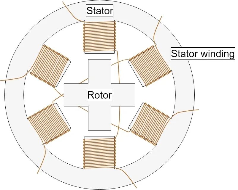
stepper motors have a fixed part (stator) and a moving part (rotor). The stator has gear-like protrusions wrapped with coils, while the rotor is a permanent magnet or variable reluctance iron core. We’ll cover different rotor structures in more depth later. Figure 1 shows a cross-sectional view of a motor whose rotor is a variable reluctance iron core.

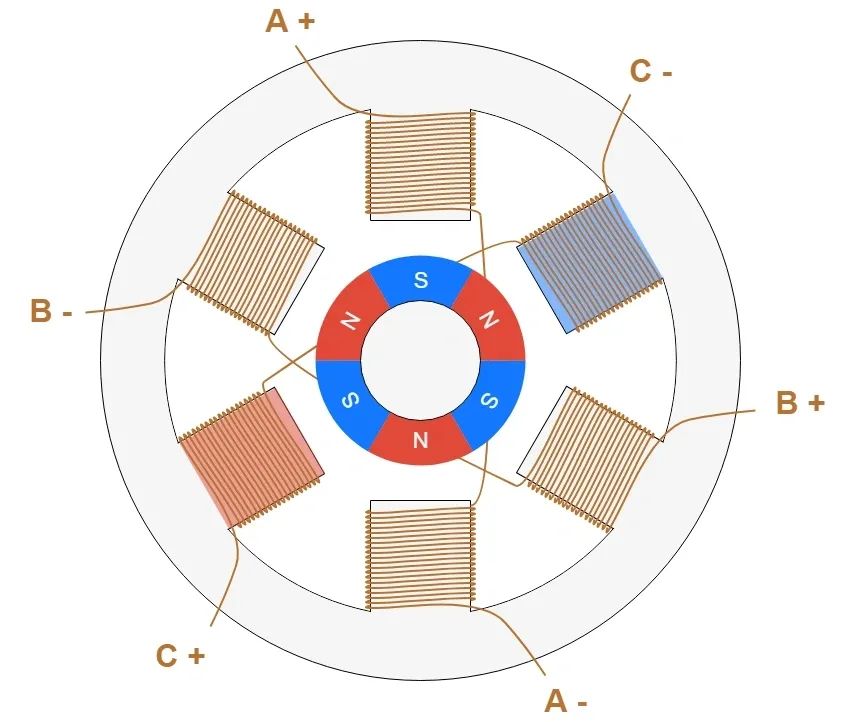
The basic working principle of a stepper motor is: energize one or more stator phases, the current passing through the coil will generate a magnetic field, and the rotor will align with the magnetic field; apply voltage to different phases in sequence, the rotor will rotate at a specific angle and Finally get where you need to be. Figure 2 shows how it works. First, coil A is energized and generates a magnetic field, and the rotor is aligned with this magnetic field. After coil B is energized, the rotor rotates 60° clockwise to align with the new magnetic field. The same situation occurs after coil C is energized. The color of the stator teeth in the figure below indicates the direction of the magnetic field generated by the stator winding.

Types and construction of stepper motors
The performance of a stepper motor (whether resolution/step size, speed or torque) is affected by construction details, which may also affect how the motor is controlled.
In fact, not all stepper motors have the same internal structure (or construction), as different motors have different rotor and stator configurations.
rotor
There are basically three types of rotors in stepper motors:
- Permanent magnet rotor: The rotor is a permanent magnet that is aligned with the magnetic field generated by the stator circuit. This rotor guarantees good torque and has braking torque. This means that the motor is resistant, even if not very strongly, to changes in position whether the coil is energized or not. However, the disadvantage is lower speed and resolution compared to other rotor types. Figure 3 shows a cross-sectional view of a permanent magnet stepper motor.
- Variable reluctance rotor: The rotor is made of an iron core that is specially shaped to align with the magnetic field (see Figures 1 and 2). This type of rotor makes it easier to achieve high speeds and high resolution, but it generally produces lower torque and has no braking torque.
- Hybrid rotor: This type of rotor has a special structure that is a mixture of permanent magnets and variable reluctance rotors. The rotor has two axially magnetized magnetic caps with alternating small teeth. This configuration gives the motor the advantages of both a permanent magnet and a variable reluctance rotor, especially high resolution, high speed and high torque. Of course, higher performance requirements mean more complex structures and higher costs. Figure 3 shows a simplified schematic diagram of this motor structure. After coil A is energized, a small tooth of the rotor N magnetic cap is aligned with the stator tooth magnetized as S. At the same time, due to the structure of the rotor, the rotor S magnetic cap is aligned with the stator teeth magnetized N. Although the working principle of a stepper motor is the same, the structure of the actual motor is more complex and has more teeth than shown in the figure. A large number of teeth allows the motor to obtain extremely small step angles, as small as 0.9°.

stator
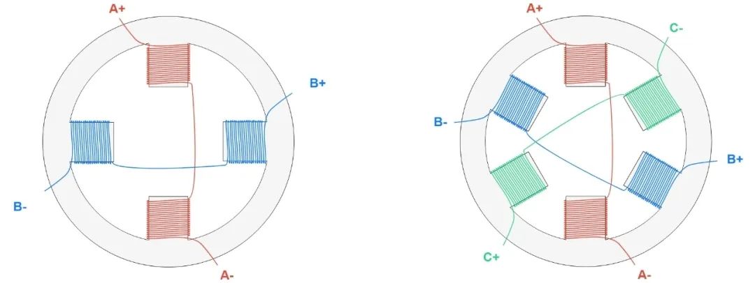
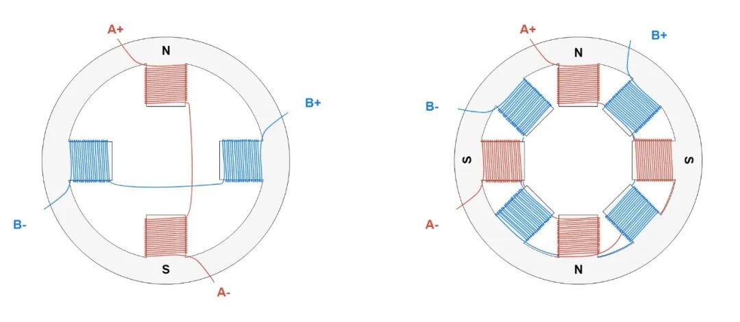
The stator is the part of the motor that is responsible for generating the magnetic field that the rotor aligns with. The main characteristics of the stator circuit are related to its number of phases, pole pairs and conductor configuration. The number of phases is the number of independent coils, and the number of pole pairs represents the main pair of teeth occupied by each phase. Two-phase stepper motors are most commonly used, while three-phase and five-phase motors are less commonly used.
Stepper motor control
We know from above that the motor coils need to be energized in a specific sequence to create a magnetic field that the rotor will align with. The devices that can provide the necessary voltage to the coil for the motor to operate properly are the following (starting with devices closer to the motor):
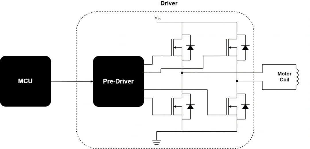
- Transistor Bridge: A device that physically controls the electrical connection of a motor coil. A transistor can be thought of as an electronically controlled circuit breaker. When it is closed, the coil is connected to the power supply, and current flows through the coil. Each motor phase requires a transistor bridge.
- Predriver: A device that controls the activation of transistors, which is controlled by the MCU to provide the required voltage and current.
- MCU: A microcontroller unit usually programmed by the motor user to generate specific signals for the pre-driver to obtain the desired motor behavior.
- Figure 7 is a simple schematic diagram of the stepper motor control scheme. The pre-driver and transistor bridge can be contained in a single device, the driver.
Stepper Motor Driver Types
There are a variety of different stepper motor drivers on the market with different capabilities for specific applications. But one of its most important features is related to the input interface. The most common input interfaces include:
- Step/Direction (Step/Direction) – Send a pulse on the Step pin, and the driver changes its output to cause the motor to perform a step. The direction of rotation is determined by the level on the Direction pin.
- Phase/Enable (Phase/Enable) – For the stator winding of each phase, Enable determines whether the phase is energized, and Phase determines the current direction of the phase.
- PWM – directly controls the gate signal of the upper and lower FETs.
Another important feature of a stepper motor driver is whether, in addition to controlling the voltage across the winding, it can also control the current flowing through the winding:
- Featuring voltage control, the drive regulates the voltage across the windings, producing torque and step speeds that depend solely on the motor and load characteristics.
- Current-controlled drives are more advanced because they can regulate the current flowing through the active coils, providing better control over the torque produced and thus the dynamic behavior of the entire system.


 2024-08-30 16:01:40
Engineering
 2024-07-26 14:09:13
Engineering
 2024-07-18 09:42:00
Engineering