- +86 19149417743
- Zhengzhou, Henan Province, China
- Mon-fri: 8am - 7pm
Get a quote

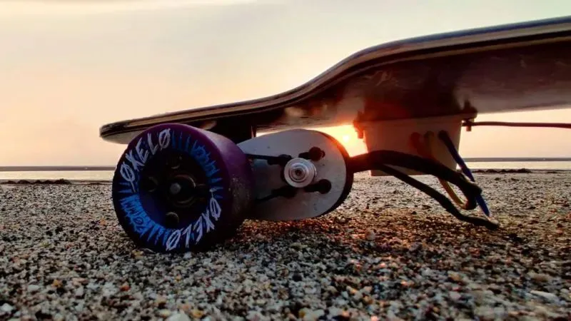
Skateboards are cool, they can not only be used for juggling, but they also function as transportation tools. So would it be cooler to add a DC motor to the skateboard and turn it into an electric skateboard? Let’s teach you how to make an electric skateboard that can reach a speed of 40km/hr (26 miles). It can last 18km on a single charge, which is enough to meet most people’s commuting needs. If you make it successfully, be sure to pay attention to safety when playing and remember to wear a helmet and necessary safety equipment at all times. In addition, the use of skateboards as a means of transportation has been banned on some urban roads, so please abide by the traffic regulations.
In the project, three phases need to be used to control the speed, so an electronic speed regulator needs to be added. The governor is the "brain" of the project. It connects the battery and motor. At the same time, it is also connected to the receiver on the remote control.
The electronic speed controller receives the "command" (PWM signal), passes it to the remote control in duty cycle, and controls the size of the throttle. It will then also control the flow of electricity from the battery to the electric motor, thereby controlling the motor's speed.
The rated power I used is 24V and 120A. According to the formula power = voltage × current, then 24×120= 2880W. The rated power of the motor is 2500W, so there will be some excess power.
The battery pack is composed of 6S 3P 18650 lithium-ion cells, six lithium-ion cells in series and three lithium-ion cells in parallel. Battery voltage is 25.2V (6×4.2).
You can also build a battery pack using lithium polymer cells, but I do not recommend that you use lithium polymer batteries, they can be dangerous if not handled properly.
Wheels, pulleys, and belts are assembled to create a drive system. The ratio of the pulley to the motor pulley is called the "gear reduction ratio." The value can be set around 2.5, but it can also be lower than 1.5 or higher than 3.
Typically, a lower speed reduction ratio is better. I used 70mm pulleys and the kit's gear ratio was a high speed gear with a value of 3.
After completing the drivetrain, connect the electronic speed regulator to the motor. The specific method is: connect the three wires of the electronic speed regulator to the three wires of the motor, then connect the battery pack to the electronic speed regulator, and finally connect the electronic speed regulator to the radio receiver.
I decided to build a radio controller using an Arduino and an nRF24L01 module, which you can also buy off the shelf. If you need to build one, you can purchase the following materials to build it.
Connect the transmitter and receiver according to the circuit provided in this step, then upload the downloaded code to Arduino, and then connect the receiver to the 5V, GND and digital pins of Arduino respectively 5 The 5V, GND and digital pins of the electronic speed regulator .
After doing the receiver test, see if the motor is spinning in the correct direction, if not, just swap any two wires from the motor and electronic speed controller and the motor will spin in the other direction.
 2024-08-30 16:01:40
Engineering
 2024-07-26 14:09:13
Engineering
 2024-07-18 09:42:00
Engineering