- +86 19149417743
- Zhengzhou, Henan Province, China
- Mon-fri: 8am - 7pm
Get a quote
A stepper motor driver is an actuator that converts electrical pulses into angular displacement. When the stepper driver receives a pulse signal, it drives the stepper motor to rotate a fixed angle in the set direction. This fixed angle is called the "step angle". Stepper motors cannot be directly connected to DC or AC power and must use a dedicated driver. The principle of the stepper driver is to use a unipolar DC power supply. As long as each phase winding of the stepper motor is energized according to the appropriate timing, the stepper motor can be made to rotate step by step. Stepper motor drivers generally need to connect pulse signals and direction signals, but enable signals are generally not connected.
The subdivision control of the stepper motor driver can adjust the speed and acceleration of the motor rotation to achieve more precise control. In addition, depending on the controller output type, the pulse and direction connections will be different. When selecting a stepper motor driver, you need to consider factors such as the motor type, voltage, current, and subdivision parameters. At the same time, you must also pay attention to the relationship between the driver's power supply and the manufacturer's design, as well as the method of modifying the direction from within the program.
Bipolar Drive: Bipolar drive is a popular drive method for two-phase bipolar motors with four conductors. By alternately reversing the current of each phase, the stepper motor operates.
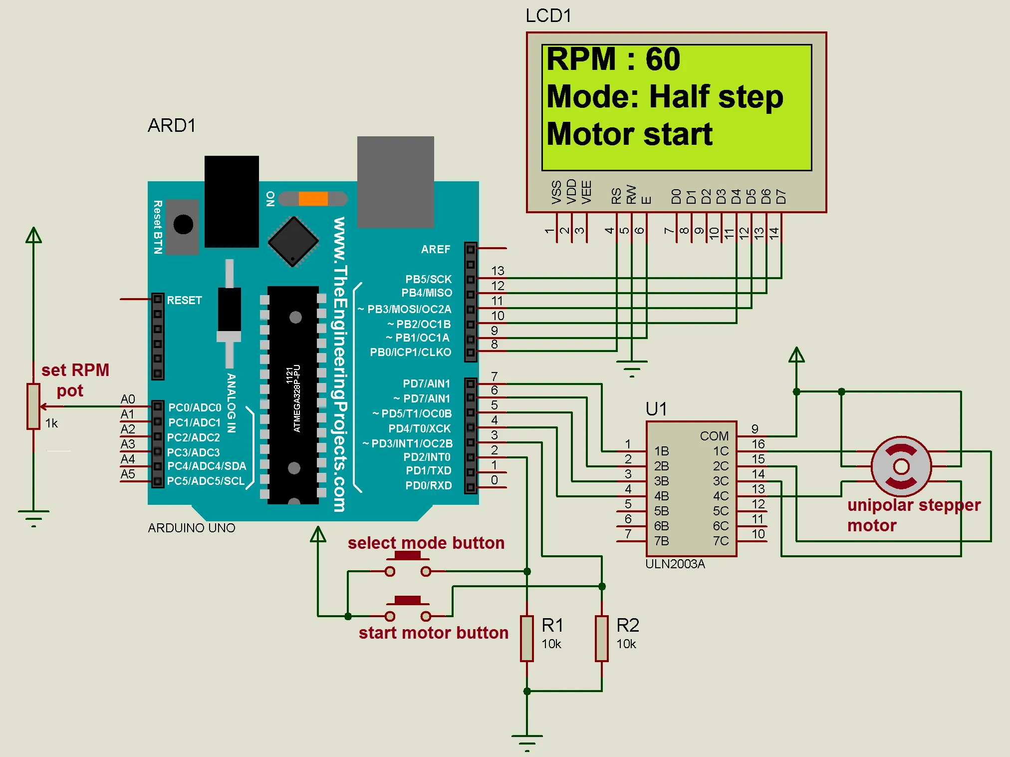
Unipolar Drive: Unipolar drive requires a motor with a center tap on each phase (6 conductors). Since there is no need to reverse the current in each phase, the driver only needs to switch the current from one coil to the other in each phase. This type of actuation results in a simpler driver, but only utilizes half the copper windings, resulting in approximately a 30% reduction in torque or force.
L/R driver: The L/R driver represents the electrical relationship between inductance (L) and resistance (R). The relationship between motor coil impedance and step rate is determined by these parameters. The power supply output voltage should be "matched" to the rated voltage of the motor coil for continuous operation. Most published motor performance curves are based on the full rated voltage applied to the motor leads.
Chopper Driver: A chopper driver is a constant current driver that is almost always bipolar. Choppers get their name from the technique of rapidly turning output power on and off (chopping) to control motor current. For best performance, it is recommended that the ratio of power supply and motor rated voltage is 8 to 1.
Other step angles: To obtain smaller step angles, more poles are needed on both the rotor and the stator. The rotor of a 7.5° motor has 12 pole pairs, and each pole plate has 12 teeth. There are two pole plates per coil and two coils per motor, so a 7.5° motor has 48 poles per step. Multiple steps can be combined to provide greater movement.
Microstepping drives: Many bipolar drives offer a feature called microstepping, which electronically breaks a complete step into smaller steps. Microstepping effectively reduces the step increment of the motor. However, the accuracy of each microstep has a larger error percentage compared to the accuracy of a full step. As in the case of full steps, the incremental errors of microsteps are not cumulative.
Full-step drive mode: In the full-step drive mode, the stepper motor controller cyclically excites the two coils of the two-phase stepper motor according to the pulse direction instructions. Each pulse moves the motor by a basic step angle, which is 1.80 degrees. This driving method has the advantages of simple structure and low cost, but it vibrates greatly when running at low speed and has relatively low positioning accuracy.
Half-step drive mode: In the half-step drive mode, when single-phase excitation is used, the motor shaft will stop at the full-step position. When the driver receives the next pulse, if the other phase is excited and remains in the original excited state, the motor shaft will move half a step angle and stop in the middle of two adjacent full-step positions. By cyclically energizing the two-phase coil with single-phase and then two-phase excitation, the stepper motor will rotate in a half-step manner of 0.90 degrees per pulse. The half-step drive mode has the advantages of twice the accuracy and less vibration during low-speed operation.
Subdivision drive mode: The subdivision drive mode performs precise current control on the two coils of the motor according to sine and cosine steps respectively, so that the distance of one step angle is divided into several subdivision steps. This drive mode has the advantages of minimal low-speed vibration and high positioning accuracy, and is suitable for application scenarios that require low-speed operation or high positioning accuracy requirements.
When selecting a stepper motor driver, you need to select the appropriate drive mode according to the actual application requirements. For application scenarios that require high precision and low-speed operation, you can choose subdivision drives; for application scenarios that require simple structure and lower cost, you can choose full-step drives; for application scenarios that require something in between, you can choose half-step drives. step drive.
 2024-08-30 16:01:40
Engineering
2024-08-30 16:01:40
Engineering
 2024-07-26 14:09:13
Engineering
2024-07-26 14:09:13
Engineering
 2024-07-18 09:42:00
Engineering
2024-07-18 09:42:00
Engineering
